Quick Start - Treon Industrial Node 6 Ex
Aug 30, 2023 · 11 minutes to read
When using the device in potentially hazardous environment
Failure to follow the instructions in this guide could result in a serious personal injury and property damage and may void warranty. Read this guide carefully before installing or using the device. Save the guide for future reference.
Treon disclaims all responsibility for work done by untrained and unauthorized personnel.
These are the personnel requirements for Ex-approved products in potentially explosive atmospheres:
All users must know about the risks of electric current and the chemical and physical characteristics of the gas and/or vapor present in hazardous areas.
The installation for Ex-approved products must be made in conformity to the international or national standards (IEC/EN 60079-17).
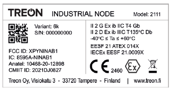
Treon Industrial Node 6 Ex is certified for use in potentially explosive atmospheres.
ATEX & IECEx Markings
II 2 G Ex ib IIC T4 Gb
II 2 D Ex ib IIIC T135°C Db
Ambient Temperature: -40°C to +60°C | -40°F to +140°F
Compliant with the following standards:
ATEX
EN IEC 60079-0:2018EN 60079-11:2012
IECEx
IEC 60079-0:2017
IEC 60079-11:2011
Product description
Treon Industrial Node is a wireless battery-operated sensor device for condition monitoring and predictive maintenance. It measures tri-axial vibration and surface temperature of rotating equipment, such as pumps, motors and compressors. Abnormal machine vibrations or high temperatures may give early signs of failure due component imbalance, misalignment, wear or improper use of equipment.
Treon Industrial Node 6 Ex variant is designed for vibration and temperature monitoring of rotating equipment in potentially explosive atmospheres.
Treon Industrial Node operates in a mesh network transmitting sensor values directly or via other nodes to a gateway, such as Treon Gateway. Typically, the data is sent from the gateway to a cloud backend for storage and further analysis.
Once the node is switched on, it starts automatically to measure and transmit data at pre-configured intervals. Depending on the configuration, the Treon Node can send raw vibration data and/or pre-calculated values, such as RMS velocity, Fast Fourier transform (FFT) and Kurtosis, to the cloud via the gateway.
Keys and parts
A. Status light
B. Orientation notch
C. Power button
D. NFC tag
E. M8 bolt
F. Nut adapter*
G. Magnetic epoxy mount adapter*
H. Glue mount adapter*
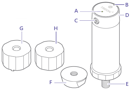
* Note that adapters F, G, and H are not included in standard sales box.
1 Mounting the Node
When mounting the sensor to a monitored equipment, it is important to consider the location of the sensor and the contact between the sensor and the equipment. Best location to attach the sensor depends on the machine and the monitored vibration source.
For best measurement quality, the contact surface in the machine should be completely flat (within 1 mil), smooth (surface texture no greater than 32 microinches) and larger than the base of the node. It’s recommended that nodes are mounted via a drilled and tapped hole directly to the machine housing.
In cases where the surface of the machine is curved or uneven, epoxy must be used between the machine surface and the node. Screwing the node to curved surface may lead to the node bolt twisting and permanent damage to the device.
CASE 1: Attach node directly to machine surface
Direct attachment between the Industrial Node and machine surface minimizes the vibration transmission route for best measurement quality. It requires a flat surface of 32 mm diameter and hole for M8 bolt with 18.5 mm of threading.
- Clean the machine surface and apply silicon grease is it.
- Apply service removable thread lock to the sensor bolt.
- Insert the bolt into a M8 hole in the machine.
- Screw the node with 30 mm torque wrench to 8 newton meters torque.
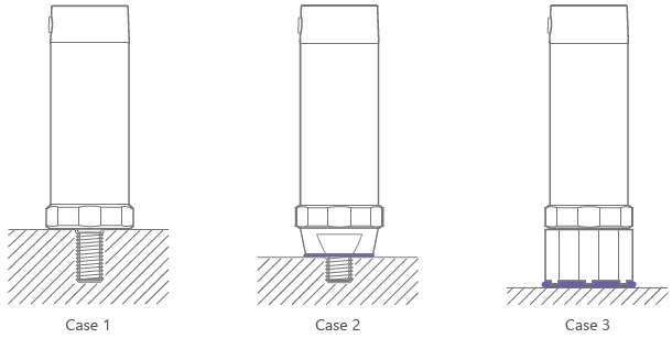
CASE 2: Attach node with nut adapter
Using a nut adapter enables attaching the Industrial Node to a spot with less available space in diameter, shorter M8 opening with less threading and with additional epoxy to uneven Surface. It requires a nut adapter, fl at surface of 25 mm diameter, hole for M8 bolt with 9.5 mm of threading and optional epoxy.
- Clean the surfaces between node and adapter and apply silicon grease on it.
- Screw the adapter nut to the sensor bolt.
- Tighten the nut to 8 Nm torque.
Without epoxy
- Clean the machine surface and apply silicon grease is it.
- Apply service removable thread lock to the sensor bolt.
- Insert the bolt into a M8 hole in the machine.
- Screw the node with 22 mm torque wrench to 8 newton meters torque.
With epoxy
- Apply Epoxy to nut adapter surface.
- Insert the bolt into a M8 hole in the machine.
- Hand tighten the sensor.
- Let the epoxy harden.
CASE 3: Attach node with epoxy or glue mount adapter
Using epoxy or glue mount adapter enables attaching the Industrial Node 6 EX without an opening for a bolt. With epoxy mount adapter the Industrial Node can also be attached to slightly uneven surface while glue mount adapter requires an even surface. Required surface diameter is 32 mm.
- Clean the surfaces between node and adapter and apply silicon grease on it.
- Screw the mount adapter to the sensor bolt.
- Tighten the nut to 8 Nm torque.
- Apply epoxy or glue to adapter surface.
- Place the node to the correct position on the machine.
- Let the epoxy or glue harden.
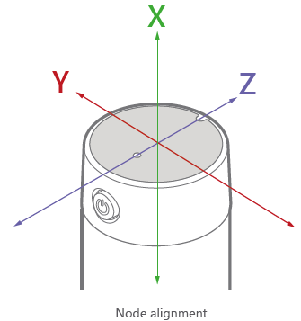
Aligning the node
For accurate interpretation of the measurement data, the centerline of the node is often aligned with the shaft of the rotating machine. This can be done by manually aligning the node with the shaft.
Manual alignment requires using the epoxy or glue mount adapter. After applying the fixative and hand tightening the sensor to the machine, align the node axis directly toward drive or non-drive end of monitored machine. Turn the node only clockwise.
For further information on the installation and alignment of your Industrial Node 6 EX, please read this article.
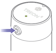
Switch on the node
Press and hold the power button until the status light turns green. If you want to switch off the node, press the power button until the status light turns red.
2 Check the connection
To see if the Industrial Node 6 EX is connected to the gateway:
Press the power button briefly. The status light turns green and goes off.
If the status light then turns green again, the node is connected.
CONNECTED
If the status light turns red, the node is not yet connected.
NOT CONNECTED
In case the node is not connected, the Treon Gateway has been powered on and the node has had time to establish the connection, the node may be too far from the gateway or surroundings are blocking the radio connection. In either case, the gateway needs to be moved closer to the node or an additional routing node can be added between the node and the gateway to help routing the data.
3 Read the Node ID
The identification number of the node is printed on the sticker attached to the node, and it can be be as well read from the QR code.
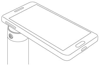
You can also use a NFC reader, such as an NFC enabled mobile phone to read the identification number: switch on NFC on the reader and touch the top of the node with the reader.
Product info
Important For important info on the safe use of your device, read the Safety Guide.
Operating frequencies: 2400MHz to 2483.5MHz
Maximum power: +4 dBm
Operating temperature range: In potentially explosive atmospheres -40 to +60°C In other normal environments -40 - +85°C
Battery Battery type: 3.6V A lithium thionyl chloride (LI-SOCI2) bobbin cell primary battery.
Do not charge, short circuit, crush, dissemble, heat above 100°C (212°F), incinerate or expose the battery contents to water.
The battery is non-removable. If the battery wears out, replace the node.
NORWAY. This device is not allowed to be used within a 20 km radius of the centre of Ny-Ålesund at Svalbard, Norway.
CERTIFICATION INFORMATION
Manufacturer Treon Oy, Visiokatu 3, 33720 Tampere, Finland.
SUPPLIER’S DECLARATION OF CONFORMITY
Unique Identifier: Treon Industrial Node, model 2111 Variant 6k
Manufacturer: Treon Ltd. Visiokatu 3, FIN-33720 Tampere, Finland https://www.treon.fi
Responsible Party – U.S. Contact Information:
OptoFidelity Inc. 19409 Stevens Creek Blvd. - Suite 250, Cupertino, CA 95014, USA http://www.optofidelity.com +1 (669) 241-8383
FCC Compliance Statement (for products subject to Part 15) This device complies with Part 15 of the FCC Rules. Operation is subject to the following two conditions:
(1) This device may not cause harmful interference, and
(2) This device must accept any interference received, including interference that may cause undesired operation.
Canada This device pleaseds with Industry Canada license exempt RSS standard(s).
Operation is subject to the following two conditions:
- This device may not cause interference, and
- This device must accept any interference, including interference that may cause undesired operation of the device.
This equipment complies with IC RSS-102 radiation exposure limits set forth for an uncontrolled environment.
Cet appareil est conforme à la(aux) norme(s) RSS sans licence d’Industry Canada.
Son utilisation est soumise aux deux conditions suivantes:
Cet appareil ne doit pas causer d’interférences et
il doit accepter toutes interférences reçues, y compris celles susceptibles d’avoir des eff ets indésirables sur son fonctionnement.
Cet équipement respecte les limites d’exposition aux rayonnements IC RSS-102 définies pour un environnement non contrôlé.
EU DECLARATION OF CONFORMITY
Hereby, Treon Oy declares that the radio equipment Treon Industrial Node is in compliance with Directive 2014/53/EU. The full text of the EU declaration of conformity is available at the following internet address:
https://www.treon.fi/documentation

Safety guide and Warranty
Introduction
Read these simple guidelines. Not following them may be dangerous or against local laws and regulations. For further information visit:
https://www.treon.fi/documentation
Care and maintenance
Handle your device with care. The following suggestions help you keep your device operational.
- Do not open the device other than as instructed in the user guide.
- Unauthorized modifications may damage the device and violate regulations governing radio devices.
- Do not drop, knock, or shake the device. Rough handling can break it.
- Only use a soft, clean, dry cloth to clean the surface of the device. Do not clean the device with solvents, toxic chemicals or strong detergents as they may damage your device and void the warranty.
- Do not paint the device. Paint can prevent proper operation.
- The node is dust and splash proof. However, it is not recommended to immerse it in water.
Safety distance
Safety distance 150 mm from the magnetic mount adapter surface must be kept due to high strength magnets.
Damage
If the device is damaged contact support@treon.fi. Only qualified personnel may repair this device.
Small children
Your device is not a toy. It may contain small parts. Keep them out of the reach of small children.
Interference with medical devices
The device may emit radio waves, which could affect the operation of nearby electronics, including cardiac pacemakers, hearing aids and defibrillators. If you have a pacemaker or other implanted medical device, do not use the device without first consulting your doctor or the manufacturer of your medical device. Maintain a safe distance between the device and your medical devices and stop using the device if you observe a persistent interference with your medical device.
Storage
Always store and use the device with covers attached. Device storage temperature is +0 to +30°C.
Recycle
Check the local regulations for proper disposal of electronic products. The Directive on Waste Electrical and Electronic Equipment (WEEE), which entered into force as European law on 13th February 2003, resulted in a major change in the treatment of electrical equipment at end-of-Life. The purpose of this Directive is, as a first priority, the prevention of WEEE, and in addition, to promote the reuse, recycling and other forms of recovery of such wastes so as to reduce disposal.
 The crossed-out wheelie-bin symbol on your product, battery, literature, or packaging reminds you that all electrical and electronic products and batteries must be taken to separate collection at the end of their working life. Do not dispose of these products as unsorted municipal waste: take them for recycling. For info on your nearest recycling point, check with your local waste authority.
WARRANTY
Treon Limited Warranty document is available at the following internet address:
https://www.treon.fi/documentation