Recommended installation locations
Accurate AI diagnosis depends on putting the sensor in the right place. This page shows where to place both Node X and Node C on common machines.
Before you start
Isolate or stop the machine if your site's procedures require it, wear the site's PPE, and always consult the asset's own product documentation before drilling or gluing anything to it.
The general rule
Pick the location that gives the best measurable vibration and temperature reading for permanent monitoring of the asset:
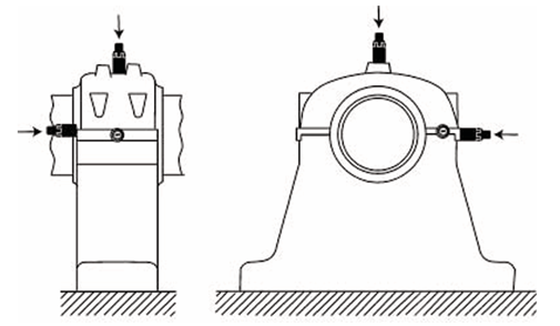
- Mount as close to the bearing load zone as feasible, directly on the machine housing. On a horizontal machine the load zone is typically the bottom half of the bearing.
- Minimise the vibration transmission path — the distance between the vibration source and the sensor. Every extra mounting interface in the path reflects signal, and rubber or plastic in the path absorbs it.
- Avoid thin covers and guards, and loosely fastened parts that can resonate — a motor fan cover, for instance.
- Avoid places where machine parts or people are likely to knock the sensor.
- Avoid surfaces above 85 °C and anywhere else that would give poor readings, damage the sensor or shorten battery life.
- Choose somewhere accessible for later maintenance or replacement without dismantling major machine parts, and away from oil spray, coolant and condensation.
How many sensors
Preferably one sensor per key bearing. Where bearings are less than 25 cm (10 in) apart, one sensor is sufficient to monitor both — valid for small motors, pumps, fans and gearboxes.
By machine type
| Machine | Where |
|---|---|
| Electric motors | Near the drive-end bearing housing |
| Pumps | On the bearing housing closest to the impeller |
| Gearboxes | On the casing near the input and output shafts |
| Fans | On the bearing housing near the fan blade assembly |
Shortest is not always best
The shortest distance to the vibration source is not automatically the best location. Think about how the vibration travels through the machine structure, and for a gearbox how it transmits through the connected components.
Horizontal machines
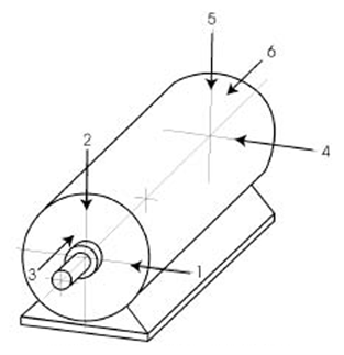
For machines with horizontal alignment or installation, the positions below give optimal readings in most cases. Remember that the bearing load zone is usually on the bottom half of the bearing.
Vertical machines
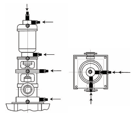
For machines with vertical alignment or installation:
Node orientation and measurement directions
Align all sensors on an asset, and across assets, in the same direction wherever possible. Unified orientation is what makes per-axis readings directly comparable between measurement points.
Align the axes as follows:
- one axis to the asset's horizontal direction,
- one axis to the asset's vertical direction,
- one axis with the asset's shaft direction (the axial direction).
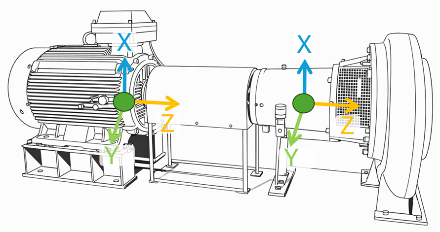
On a Treon Industrial Node X, use the safety-screw opening as the visual reference — it marks the node's Z-axis.
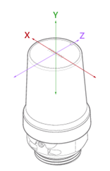
Always measure at least one radial direction (vertical or horizontal). Take axial measurements at least at axial load-carrying (thrust) bearing locations.
Not every mounting method can be oriented
Manual alignment of a Treon Industrial Node X requires the Orientation Adapter, a magnetic glue adapter, or direct gluing. The Bolt Mount Adapter does not allow axis rotation during installation or afterwards.
A Treon Industrial Node C is glued on, so it can be oriented freely in any direction — which means there is no excuse for not aligning it. Align it the same way as a Treon Industrial Node X: one axis axial with the shaft, one horizontal, one vertical. See Mounting.
Mounting preference
Prefer bolt mounting with spot-face drilling for the best frequency response, using the Orientation Adapter so the node can be aligned properly.
Do not glue where a glue failure and a detached sensor could damage the machinery.
Good mounting practice
Example 1: ideal sensor orientation on a horizontal machine. The sensor axes align with each other and with real-world horizontal (Y), vertical (X) and axial (Z) directions, which makes the data much easier to analyse.
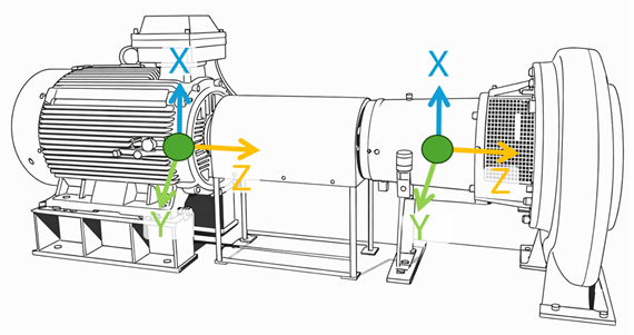
Example 2: a large motor and overhung fan unit. One sensor close to each of the four bearings — two on the motor, two on the fan bearing housings — with orientations aligned, so data can be compared across sensors.
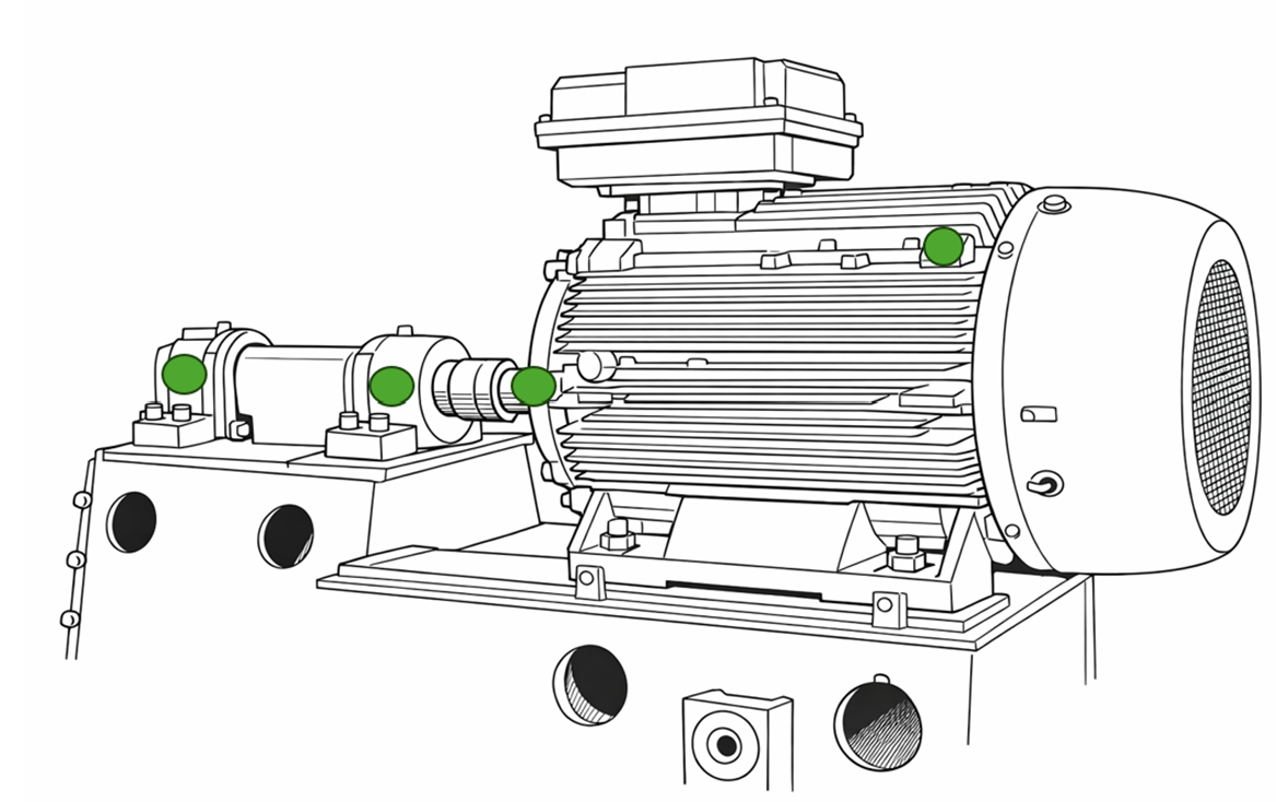
Example 3: a large gearmotor. Two sensors on the motor — one at the non-drive end (NDE), one at the drive end (DE) — and two on the gear, one near the input shaft and one near the output shaft.
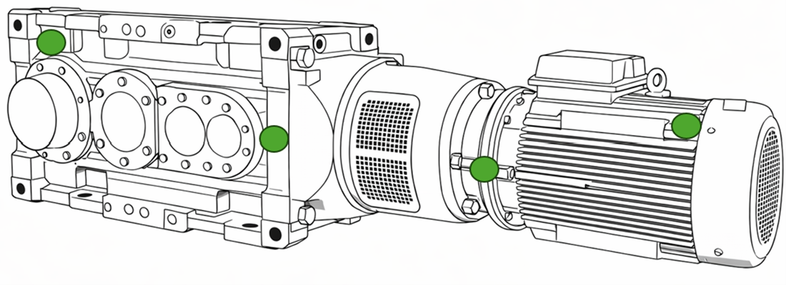
Example 4: a small gearmotor. Two sensors are enough: one on the motor (the DE usually offers a better mounting surface than the NDE) and one near the gear output shaft.
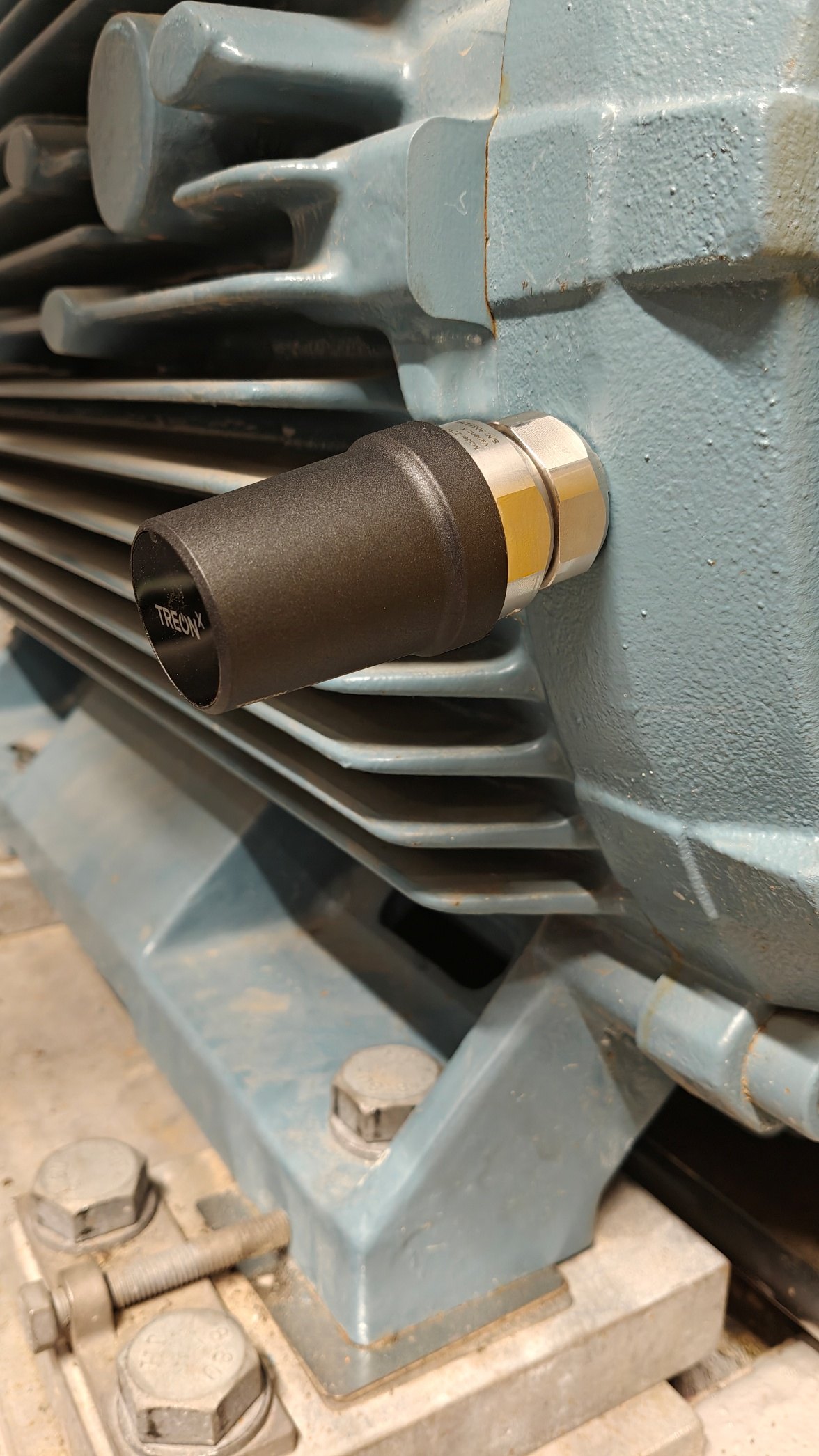
Example 5: a bolt-mounted node in place. A Treon Industrial Node X installed on the drive-end (DE) motor end shield of an electric motor — on the solid casting next to the bearing housing, not on the cooling fins beside it.
Improper mounting locations
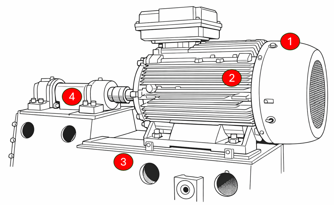
Mistake 1: motor cooler fan cover. The sensor picks up mostly cooler-fan vibration, which tells you nothing about the asset's condition.
Mistake 2: motor cooler fin. The sensor picks up mostly cooler-fin vibration — again not useful.
Mistake 3: machine base. Too far from the source of vibration; you get a dampened, mixed-up signal from the whole asset rather than the part you meant to monitor.
Mistake 4: shaft cover. Same problem — too far from the source, dampened and mixed.
Troubleshooting
I can't identify the best mounting location. Finding the ideal place is not always straightforward and takes some experience. Re-read the rules above and decide which vibrations you actually want to measure. If you are still unsure, consider a specialist consultation with Treon.
The data doesn't match what a previous sensor showed. Check that the sensor is mounted somewhere that picks up data of comparable quality to the previous sensor, that the mounting method was executed correctly and suits the location, and that both sensors were aligned comparably — and that you are comparing the same axes.
The data doesn't match another sensor currently on the asset. Two sensors can never be mounted in exactly the same location, so some difference is expected. Beyond that, check the same three things: comparable location, correct mounting, comparable alignment and matching axes.